 This is the second in our series of posts where we will be sharing our drawings for the White Horse CAD Wobbler Engine. This week we will look at the Wobbler Engine Piston.
Over the next 3 weeks, we are going to be looking at the piston sub-assembly. Next week we will look at the piston bearing bush and in the third week, we will discuss the completed sub-assembly.
Let’s look at some of the pistons features in a little more detail. If you would like to refer to the PDF engineering drawing it can be found by clicking here… P9999-12101_Rev1
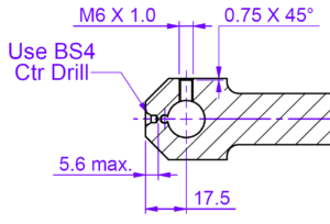 Considering how a part will be made is a really important part of product design. The piston has been designed to be manufactured using both turning and milling processes. This could be on a single multi axis CNC machine or on a number of different manual or CNC machines. Whichever process is used, the outcome will be the same. One small feature that will allow the part to be made from a minimum amount of material is the addition of a centre drill feature in the bearing end. The centre drill size has even been identified as BS4.
Not many people will realise that the BS in BS4 does not stand for “British Standard” but actually stands for “British Slocomb” and the 4 denoted the its size.
Without the addition of the centre drill information in the drawing the maker may use a slightly longer billet of material and remove the part containing the centre as a final operation. This would add an unnecessary machining step and increase the required bar length.
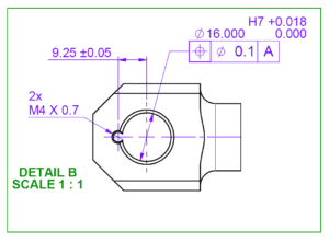 The bearing end of the piston has 2 holes that overlap. The smaller hole is also taped from either end. This may look difficult to manufacture. But if the smaller hole is drilled and tapped on both sides before starting the larger hole then it is relatively simple to machine. The biggest challenge will be creating the 16Ø H7 tolerance. Perhaps it would be best to start by drilling a smaller hole (14Ø would be ideal). The hole could then be opened with a 5/8″Ø (15.875mm), or similar end mill. This will leave less than 0.2mm to remove using an adjustable boring head on a milling machine.
Don’t miss the next in the series… … sign up here…
Have a project you would like to discuss?… Contact us here…


You must be logged in to post a comment.