 Today’s blog is the ninth in our series of posts where we share drawings for the White Horse CAD Wobbler Engine. This week we will look at the Wobbler Engine Base Sub Assembly.
Next week we will look at the Wobbler Engine Piston Housing.
Let’s look at the Wobbler Engine Base Sub Assembly in more detail. If you would like to refer to the PDF engineering drawing, click here..P9999-13001_Rev1
 The Wobbler Engine Base Sub Assembly forms the back bone of the engine. All major components such as the main shaft, piston, and piston block will be fitted to the base. Therefore, all bolts must be tightened adequately, and the vertical support must be perpendicular to the wooden base.
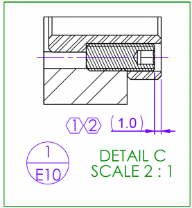
Detail C on the left shows how the socket set screws hold the flywheel bearings into place. You can see that the top of the screw is below the surface of the bearing and tightens against the base of the flat-bottomed hole. This will stop the bearings from rotating and hold them against the face of the vertical support.
It is also important to ensure the vertical support is assembled in the correct orientation. The exploded isometric view on sheet 2 of the drawing details exactly how the components fit together.
Don’t miss the next in the series… sign up here…
Have a project you would like to discuss?… Contact us here…


You must be logged in to post a comment.