Wobbler Engine Base
 Today’s blog is the fifth in our series of posts where we share drawings for the White Horse CAD Wobbler Engine. This week we will look at the Wobbler Engine Base, the first part of the second sub-assembly.
Next week we will look at the main support, the backbone that all the main parts attach to.
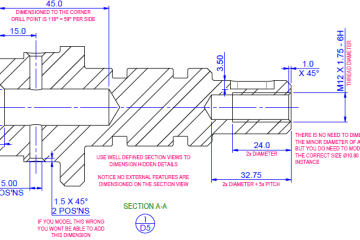
Let’s look at one of the base’s features in more detail. If you would like to refer to the PDF engineering drawing, click here… P9999-13101_Rev1

Most engineers will be familiar with geometric tolerating, but the casual maker may not understand them.
 The 200mm width of the base had a datum symbol “A” attached to it. The two holes are at 75mm centres with a tolerance of ±0.3mm. This tolerance is not declared on the drawing, but if you look at the title block, you will notice the “unspecified dimensions” section. The hole’s centre dimension has one decimal place, so the tolerance is ±0.3mm.
Now, back to that geometric tolerance: the geometric tolerance frame is split into three sections:
- The type of tolerance (Symmetry)
- The allowed error (0.2mm)
- The Datum from which the tolerance relates (A)
Consequentially, the centres can be between 74.7mm and 75.3mm AND must be symmetric about the width within 0.2mm.
But why have we used geometric tolerances? The holes need to be in the middle of the base for the engine to fit together correctly. This means that regardless of the finished width of the base (199.7mm to 200.3mm), the two holes must be symmetric about the centreline. Had we dimensioned the holes from one edge, they may not be symmetric.
Don’t miss the next in the series … sign up here…
Have a project you would like to discuss?… Contact us here…


You must be logged in to post a comment.