 We are certain every design engineer on the planet has come across the problem of creating a library of standard parts at one point or another. So we have created some files that will hopefully make the task a lot less bothersome.
We find the most important thing when creating a library of standard parts is to work from a single set of source files for each type of fastener. This makes changing between parts in assemblies much quicker. At the core of our standard part library is a series of fully parametric part files that cover most of everything a design engineer will need:
- Cap Head Screws
- Countersunk Screws
- Nuts
- Bolts
- Button Head Screws
- Shoulder Bolts
- Extension Springs
To receive your FREE copy of these part files and start building your own library of standard parts, simply complete the short form below.
Most of the fasteners can be created by adjusting a few global variables. Just visit your favourite fastener suppliers’ website, get the information required, and populate the information using the “Manage Equations” dialogue box. You can find this by right-clicking on the equation list in the feature manager.
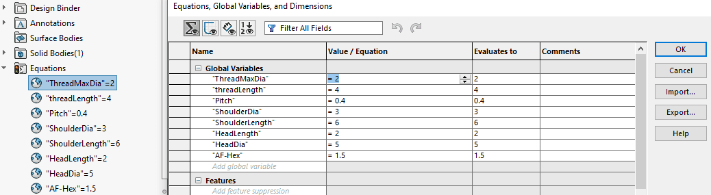
Adjust the global variables
Once you have populated the fields and closed the dialogue box, you will have a model file of the fastener you need. Then simply click, File, Save As, and give it a name. You’re welcome to use our naming format to get started if you’d like.
Mxx-yy-SKT-CAP-SET-zz
- xx = Thread Size
- yy = Length
- zz = material
For example M4-18-SKT-CAP-SET-A4
We’ve parametrically tied the description back to the global variables, so the size is correctly reported when populating BOM’s. This means you don’t have to edit the description in every part.
The Spring
 The spring is a little more involved than the other files, but we think it’s worth the effort. The first thing to notice is there are two configurations, Free, and Compressed. This means the model can be used in a compressed state within your assembly files (no more springs that don’t look right).
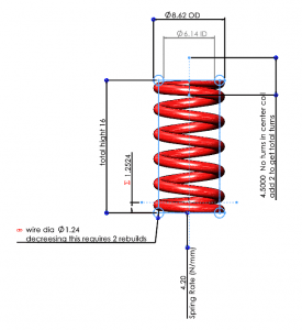
Adjusting the spring is a case of changing a few dimensions in the “Control Sketch.”
- Outside Diameter of the spring
- Wire Diameter
- Total Height (change in both configurations)
- Free Length
- Compressed Length
- Number of turns in the middle section.
- This is always 2 less than the total number of turns and does not need to be a whole number
- Spring Rate in N/mm
- This does not affect the model but is used in the description.
Once completed, it’s another simple File, Save As, and give it a meaningful name. Again, you’re welcome to use our name format.
od-wd-nc-fl-CS-zz
- od = Outside Diameter
- wd = Wire Diameter
- nc = Number of coils (remember this is 2 more than the figure aged)
- fl = Free Length
- zz = Material
For example 8.62-1.24-6.5-16-CS-SS
You must be logged in to post a comment.